Reference for the public RC1 Trial. The embedded version is 0.1.0-beta.20-dev.1. Procedures are grounded in the matching source; the testing record explains which checks were repeated in Windows. FiberAtlas documents user-authored work and does not issue engineering or field acceptance.
CHAPTER 01
Download, install, and identify RC1
FiberAtlas Beta 2.0 RC1 is a Windows evaluation release for OSP mapping and project documentation. Use a small fictional project while learning. The public Trial lasts 14 days from the original first run on the device.
- Open https://beta.fiberatlas.app/trial. Enter your name and email, add a company only if you want to, and review the download consent.
- Request the confirmation email. Open the message from FiberAtlas and use its confirmation link within 30 minutes.
- After confirmation, download Setup for an installed application or Portable for the portable package. The website download session lasts 24 hours; it is separate from the app's 14-day Trial.
- Verify the filename, SHA-256, and valid signature against the current download page. The certificate signer is John Philipe Kemmler; ordinary application publisher metadata is FiberAtlas Software.
- Launch the chosen package. Make any location choice yourself. If location is declined, you can navigate the map manually.
- Open Help, then About FiberAtlas. Record the app version and build ID before asking for support.
Match the build, not just the label
The public release label is 0.1.0-beta.20-rc1. The embedded app version and executable filenames retain 0.1.0-beta.20-dev.1. The RC1 build is fa-0.1.0-beta.20-dev.1-36975d4d9555a00a. The Testing & results page publishes the complete package hashes.
If the link or Trial has expired
Request a fresh confirmation link if the website session has expired. Downloading again does not reset an expired app Trial. Preserve your project files and contact support if the protected Trial status seems wrong; do not delete licensing or protection files.
↑ ContentsCHAPTER 02
Your first project
This walkthrough creates a small practice record: one handhole, a short distribution route, a named folder, a saved project, and a GIS handoff. It does not create an engineered design.
- Choose Start New or Create new project. Give it a name such as SYNTHETIC - First practice.
- Draw a Local Project boundary when offered, or set it later from the Local Project menu. A boundary is optional organizational geometry.
- Choose a handhole point tool and click a suitable practice location. Return to the Select arrow when finished placing points.
- Choose Distribution. Click the first route vertex, add at least one more, and press Enter to finish. Select the arrow again when finished drawing.
- Select the point and route in turn. Give them distinctive names and a short note. Check that the selected record in the tree matches the object on the map.
- Create an Area or Phase folder from the project tree and review its visibility and membership. Review Project Quantities for the intended scope.
- Save a permanent .fiberatlas file to local storage. Close normally, reopen that exact file, and confirm the names, route, and note.
- Export a new KMZ using a deliberate scope and sharing profile. Open the KMZ in the intended recipient's viewer and compare the expected records.
What success looks like
The native file reopens with your recorded geometry and properties. The separate KMZ contains the chosen GIS content. A drawn line touching a point does not, by itself, establish an optical connection or service assignment.
Practice before changing real work
Use Help's supplied fictional samples for network and splicing exercises. When you change a sample, save it under a new name. Preserve the original so you can repeat the exercise from a known starting point.
↑ ContentsCHAPTER 03
Find your way around the workspace
The map, project tree, and properties panel describe the same active project. Selecting an item should keep its identity clear across those views.
- Use the project tree to find Local Projects, Areas, Phases, type folders, routes, and assets. Expand the intended branch before editing.
- Use the Select arrow for navigation and selection. Drawing tools can remain active after placing an object; switch back to Select to avoid placing another one.
- Use the properties panel to inspect and edit the selected record. Check the name and type before applying an edit.
- Resize the panels to suit your monitor. Use Map Focus, or Ctrl+Shift+M, to temporarily hide the project and properties panels. Use the same command to return.
- Open Settings for theme, Comfortable or Compact density, units, language, layout, and recovery preferences. Save settings when you want to keep a change.
- Use Ctrl+K to focus project-tree search. Enter can act on a single exact result; Escape clears or exits the current search or editing context as appropriate.
Location and online reference
Settings includes Map & location > Ask for location at startup. Turning the preference on restores a prompt; it does not grant Windows location permission. Basemap and address-search services need internet access and remain reference sources.
Display and language
Comfortable spacing is the default. Compact gives more working room. Some newer technical workflows remain English-only even if the wider interface is set to Spanish. Broader display-scaling coverage is still under test; include scaling and window size when reporting a layout problem.
↑ ContentsCHAPTER 04
Save, reopen, and recover your work
The native .fiberatlas file is the complete working record. A GIS export, printed report, or saved layout is a different kind of output and is not a substitute for a native backup.
- Use Save or Ctrl+S at meaningful milestones. On a new project, choose a permanent local filename and location.
- Use Save As or Ctrl+Shift+S to create a deliberate copy before experimenting or making a new revision.
- Check the status message after saving. A failed or cancelled save does not mean the project is safely on disk.
- Close the application normally, then use Open or Recent to reopen the exact intended copy. Verify the project identity and important records.
- Keep independent backups of the native file. Make backup copies when the application is closed or when a successful save has completed.
- After an interruption, review an offered recovery record before saving it. Preserve the permanent file until you have confirmed which version contains the intended work.
Autosave is recovery protection
Autosave recovery is enabled by default at a five-minute interval and can be adjusted in Settings. Recovery copies stay on the device and do not silently replace the permanent project. They reduce the effect of interruption but do not replace intentional saves or independent backups.
If saving fails
Keep the application and unsaved work available while you record the error. Check the destination and available space. Use a new local copy if safe. Do not assume a different filename shrinks saved-run history or fixes corruption. A read-only or foreign-owned Work File must remain read-only.
↑ ContentsCHAPTER 05
Organize Local Projects, Areas, and Phases
Use hierarchy to keep a working scope understandable. Organizational boundaries and folder membership affect review and output; neither defines a legal or approved service area.
- Choose the intended Local Project in the project tree. Confirm it is active and writable before adding records.
- Choose Folder and select Area, Phase, or General Folder as appropriate. Name it for the work you need to review.
- Open Folder Properties to inspect its type, parent, and visibility. Add a child folder only within a supported hierarchy.
- Draw, frame, edit, or remove an optional boundary from the folder's controls. Finish a polygon with at least three vertices.
- Review the actual contents and their folder membership. Hiding a parent hides its descendants from the map.
- Before printing or exporting, check whether the chosen scope uses an organizational boundary, membership, or visible map content.
Type folders are managed
Catalog-managed type folders retain their standard name, type, and parent. You can control visibility; they are not arbitrary folders to rename into a different asset type. Move or remove contents before deleting an ordinary folder that must be empty.
Maps and materials can use different scopes
Map sheets use visible geometry. Materials default to All Recorded and can be switched to Visible Only where offered. A hidden item can still belong to an All Recorded materials total. Read the scope label on each output rather than assuming it matches the screen.
↑ ContentsCHAPTER 06
Draw and edit points, routes, and boundaries
Create only geometry that you intend to document. The available tool name tells you the record category; the application does not turn that choice into an engineering specification.
- Select the point tool for the intended asset, then click the map to place it. Add its name and properties and return to Select when done.
- For a route, choose the category, click successive vertices, and press Enter after at least two vertices to finish. Escape cancels an unfinished draft.
- Select an existing point to inspect it. Use its supported move action when changing location; cancel if the wrong record is selected.
- Select a route and use the available vertex-edit or extension controls. Review the whole route after a move, extension, or removal.
- Use Undo and Redo to review a recent change. Save once the intended geometry and properties are correct.
- Use the Measure tool for a temporary measurement. Finish it with Enter. A temporary measurement does not create a documented cable route.
Common tools
The catalog includes structures such as poles, pedestals, handholes, vaults, cabinets, FDPs and splice closures; service and equipment points; and route categories such as Backbone, Distribution, Drop, Strand, Conduit, Innerduct and Microduct. Use the current menu for available placement types. Legacy records can carry categories that are not offered for new placement.
Snapping and associations
Review what was actually recorded after snapping or aligning. Nearby geometry is a candidate for review, not proof of a physical connection. In older files, an explicit Align action can move an asset and attached route endpoints; inspect the result before saving.
↑ ContentsCHAPTER 07
Names, properties, styles, and numbering
Keep each record understandable without relying on its color or position alone. Names, notes, types, and status should describe what the user knows.
- Select an object and confirm its name, type, and project before editing its properties.
- Record the intended name, status, notes, and supported attributes. Leave an unknown value unknown instead of entering a convenient guess.
- Use the project's style controls when the map needs a consistent symbol, color, or line treatment. Review a representative point and route after the change.
- Use numbering controls only after reviewing their scope and preview. Check for duplicate or unintended names before applying.
- Add photographs or supporting notes deliberately. Review the file and its content before placing it in a record that will be shared.
- Save, then inspect how the record appears in the tree, quantities, and a representative export or report.
Identity is more than a display name
Features, cables, ports, evidence records, and saved runs use stable identities. Renaming an object does not make a similarly named imported object the same record. Historical results retain the identities of their captured source.
Labels are documentation
A status label or color does not establish field completion, ownership, compliance, or approval. Standard fiber and tube colors are useful for identifying positions; they are not network-test results. Custom labels should be clear enough for someone else to interpret.
↑ ContentsCHAPTER 08
Review route associations and service intent
Map associations, housed equipment, strand-level connections, and intended service assignments answer different questions. Review each in its own controls.
- Select a route and open Route associations. Choose the Local Project, Area, or Phase scope shown in the panel.
- Review Direct connections and the identities of the listed point assets. Equipment housed at a connected container may appear beneath that container.
- Review nearby alignment candidates in an older project before using Align. Use Remove connection when an explicit exception is intended.
- Select a service endpoint and review its intended assignment. A source, cable-end strand, or port must be chosen explicitly where the workflow requires it.
- Open the appropriate splice or optical-equipment controls to inspect the actual recorded path. Do not substitute a map association for a strand or port connection.
- Run a scoped Network Test to compare the reached source with the intended source and review any incomplete, conflict, or wrong-assignment result.
A reachable service can still be wrong
If two services reach each other's intended sources, both may be physically reachable in the model while their assignment checks fail. Missing intent must remain incomplete rather than being guessed from proximity or the first reachable path.
Housed is not connected
Placing equipment in a cabinet or documenting its inventory does not wire its ports. A route passing a container does not create an internal equipment path. Keep the container relationship, external connection, and internal connection records explicit.
↑ ContentsCHAPTER 09
Review lengths, slack, quantities, and conduit
Project Quantities summarizes recorded data in the chosen scope. It is useful for reconciliation, but it does not add engineering allowances or create a procurement order.
- Open Project Quantities when needed; it starts closed to preserve map space.
- Choose the intended project or folder scope and review the grouping and visibility rules.
- Compare point counts and route lengths with the records that contribute. Confirm project distance units before interpreting a number.
- Review documented slack separately. Total documented cable combines mapped length with slack explicitly allocated to the route.
- For Conduit, Innerduct, or Microduct, choose a nominal type/size before drawing or leave it Unspecified. Presets include 1.25-inch HDPE, 2-inch HDPE, 4-inch Metal casing, and 4-inch PVC.
- Use Custom for another documented description, up to 80 characters. Edit an existing route through Route documentation.
- Review any deliberate option to update unspecified existing routes. Already documented routes keep their values. Save and check the resulting quantity groups and route inventory.
Project defaults are deliberate
Double-click or right-click a route tool to change that project's drawing default. Changing the default normally affects new routes. A route type change that would remove conduit documentation requires confirmation.
Do not infer allowances
Mapped length does not automatically include sag, reserve, waste, bend allowances, or purchase rounding. Conduit type/size fields are nominal labels, not wall thickness, SDR, inside diameter, duct fill, loading, or bend-radius calculations. Detailed legends can disclose omitted entries; use the complete Route Footage inventory when needed.
↑ ContentsCHAPTER 10
Document equipment and container contents
The equipment workspace distinguishes mapped contents from non-spatial inventory and from explicit optical equipment. Choose the kind of record that matches what you need to preserve.
- Select a supported host container and open its contents or equipment controls.
- Review mapped contents separately from non-spatial equipment records. Confirm which host owns the record.
- Add a catalog item or create a custom equipment type using the available form. Enter a clear name, quantity, and documented attributes.
- Review a custom type before saving or reusing it. Cancel to discard an unfinished change.
- For a supported optical host, choose Add optical equipment. Select a suitable generic preset or custom device, and inspect its port count, roles, connector and polish information.
- Use Splice Lab · Equipment to reopen the host's optical devices. Review each device and its explicitly documented connections before saving the project.
Generic presets need review
Splitter, patch-panel, pigtail, patch-cord, and custom-device records provide a structure for documentation. A generic preset is not a verified manufacturer specification. Confirm component identity and source data before using an optical loss value.
Editing and removal
Occupied or referenced ports can prevent a change. Review the specific conflict rather than removing unrelated connections to make a form succeed. Container inventory quantities do not automatically create ports, internal paths, or field evidence. Read-only projects cannot record these edits.
↑ ContentsCHAPTER 11
Record optical ports and connections
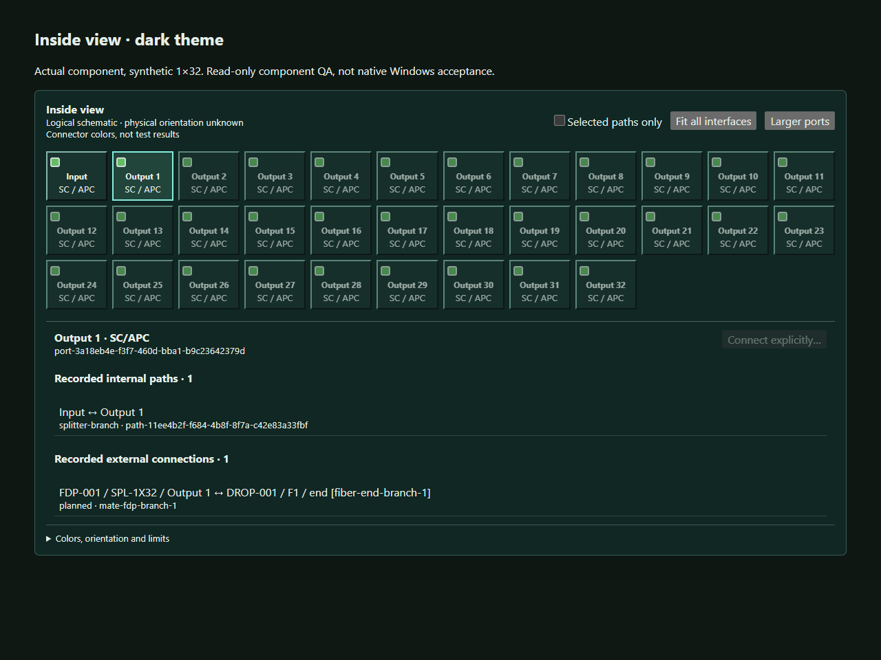
An optical path needs explicit endpoints and internal relationships. The Inside view is a logical schematic; it is not a physical orientation drawing.
- Open Splice Lab · Equipment for the intended host and select the exact device.
- Inspect its port IDs, roles, sides, lanes, connector, and polish information. Confirm the input/common side and intended output branch.
- Record supported internal paths explicitly. For a splitter, inspect the common-to-branch relationships rather than assuming every visible port is connected.
- Use the connection controls to choose the exact external endpoints. Review occupied, duplicate, unsupported, or dangling-reference messages.
- Inspect the Inside view. Use selected-path filtering, fit controls, or larger ports where useful for review.
- Cancel an unintended draft, or deliberately record the intended change. Save the project and use Network Tests to review the documented path.
Logical appearance
Connector colors describe connector information, not a pass/fail result. A line in the schematic describes a recorded logical relationship; physical orientation can remain unknown. Do not infer installed status from a graphical highlight.
Terminal boundary
Use only the connection and termination actions actually exposed for the selected host. This release does not provide a general terminal-internal splicing workflow. A connection cannot be made complete by guessing a missing internal path.
↑ ContentsCHAPTER 12
Open and prepare the Splicing Laboratory
Start by identifying the case, cable ends, and logical tray. A clean preparation step prevents an attractive diagram from hiding the wrong records.
- Select the intended splice-capable case or container and open the Splicing Laboratory.
- Review Identify/setup information. Confirm the selected host and the cable ends actually associated with it.
- Use the cable browser to inspect recorded use, cable-end identity, fiber count, and any occupied or conflicting positions.
- Select the first cable end, the logical tray, and the second cable end for the Workbench.
- Inspect the tube and fiber positions on both cable faces. Check direction and the actual selected range, especially when counts differ.
- Use the tray controls to select or manage the intended logical tray. Review references before renaming, changing, or removing a tray.
- Keep Suggested Draft work separate from existing recorded splices. Close or cancel a draft when it is not the intended mapping.
Logical tray versus physical proof
A tray record organizes splice documentation. It does not verify the physical tray, installed routing, bend radius, enclosure capacity, or field condition. Cable orientation and unknown states must remain explicit.
Existing recorded use matters
Do not overwrite an occupied position simply because a drawing looks tidy. Use the recorded-use browser and the review messages to understand whether a strand is already mapped, reserved, excluded, or in conflict.
↑ ContentsCHAPTER 13
Review a draft and apply splice records
Apply Splices is the deliberate step that records reviewed splice mappings. Selecting strands, creating a suggestion, or saving a project is not the same transition.
- With the exact cable ends and logical tray selected, create the intended strand mapping using the available Workbench or quick-splice controls.
- Inspect the visible Suggested Draft. Review its first and last strands, range, direction, and tray.
- Run or read the review results. Resolve duplicates, occupied positions, exclusions, unsupported connections, and other conflicts.
- Use draft edit, Undo, Redo, or Cancel controls to adjust or abandon the proposal without presenting it as recorded work.
- Choose Apply Splices only when the reviewed mapping is the one you intend to record.
- Reinspect the recorded matrix or cable-use view. Confirm the exact cable IDs, strand pairs, case, and tray.
- Save the native project to retain the recorded change on disk. Review any installed or field-completion state separately.
Different kinds of state
Suggested Draft is a proposal. Recorded means the user deliberately saved a mapping into the project model. Installed or field-complete describes a separate documented state. None of those automatically proves optical performance or engineering acceptance.
Review and handoff
Use the read-only Splicing popout for additional screen space where available. It is not a second editable project. Matrix and booklet output must use recorded mappings; an unapplied draft must not be quietly promoted into a recorded instruction.
↑ ContentsCHAPTER 14
Quick Light Trace and Network Tests
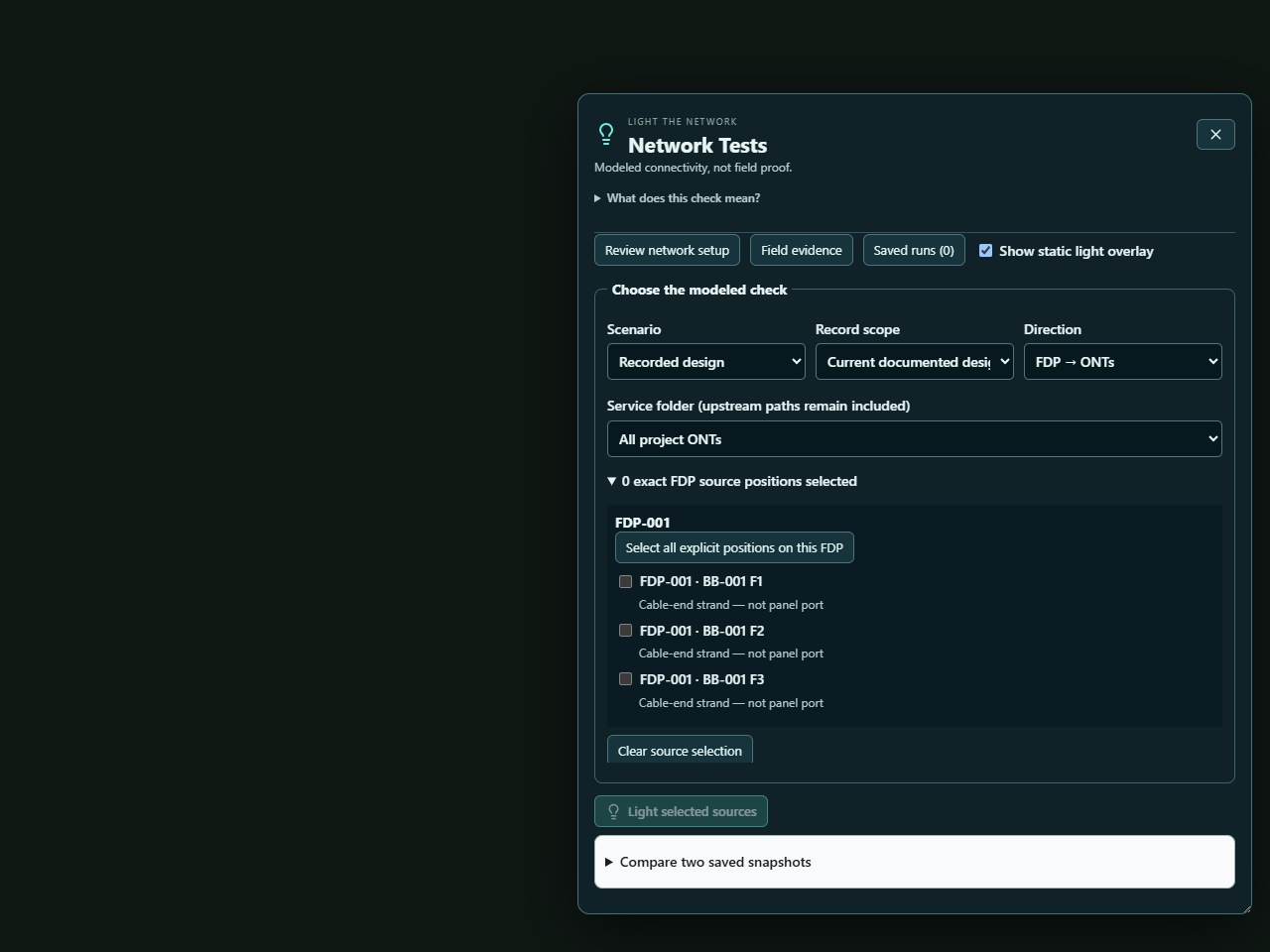
Quick Light Trace provides a temporary view of modeled continuity. Network Tests adds explicit scenario, lifecycle, source, direction, and service scope for a repeatable check.
- On a supported source or service endpoint, use the right-click Quick Light Trace action. Inspect the highlighted modeled route.
- Click away or press Escape to clear the temporary highlight. This does not alter the project.
- Open Network Tests and choose Recorded design or draft simulation. Select the current documented design or installed-record scope as appropriate.
- Choose forward or reverse direction. Select exact source positions and the intended service or folder scope. A folder's service selection can still require upstream paths.
- Run the check. Review each service's intended and reached source, exact path references, and issue details.
- Treat cancelled, limited, stale, incomplete, and failed results according to their labels. A green reachability result is not automatically a correct assignment.
- Use cut-impact or two-snapshot comparison controls only in their explicit read-only simulation/review scope.
Branch-specific review
For a supported splitter, a forward trace can follow its documented branches. A reverse trace from one service should return through that branch to the common source rather than flood sibling services.
Before rerunning
If the project or selection changes, rerun against the intended current source. Do not use a stale result as though it were newly calculated. Save a completed run when you need to preserve the exact source and result for later review.
↑ ContentsCHAPTER 15
Review modeled optical loss
Optical review uses the selected path, wavelength, documented lengths, components, and profile. Its result is separate from modeled connectivity and from measured field evidence.
- Start with an explicitly scoped Network Test and select the service or branch you want to examine.
- Choose an optical profile and wavelength. Review the profile's source, revision, applicable components, and stated assumptions.
- Inspect the path ledger for fiber lengths, component losses, connections, and unsupported or missing values.
- Review minimum, typical, and maximum calculations only for the inputs actually present. A known subtotal is not a complete end-to-end answer when gaps remain.
- Enter or select reviewed transmitter, receiver, sensitivity, overload, and criterion data only where you have a valid source.
- Check the exact branch, direction, wavelength, and reference boundaries before exporting the report or comparing a measurement.
Unknown is useful information
The starter catalog is incomplete. Missing length, component, wavelength, profile, or criterion data must remain Unknown or Not evaluated. Do not enter zero merely to make a result complete. A model can show connectivity while optical evaluation remains incomplete.
Loss and power are different
Insertion loss is expressed in dB; optical power is expressed in dBm. A modeled loss budget, a receiver power comparison, and an actual instrument observation are different records. Use the measurement method and unit that match the evidence.
Purpose
These tools organize reviewed calculations and their sources. They do not select cable design, certify installed performance, or grant owner acceptance.
↑ ContentsCHAPTER 16
Save and reopen network test history
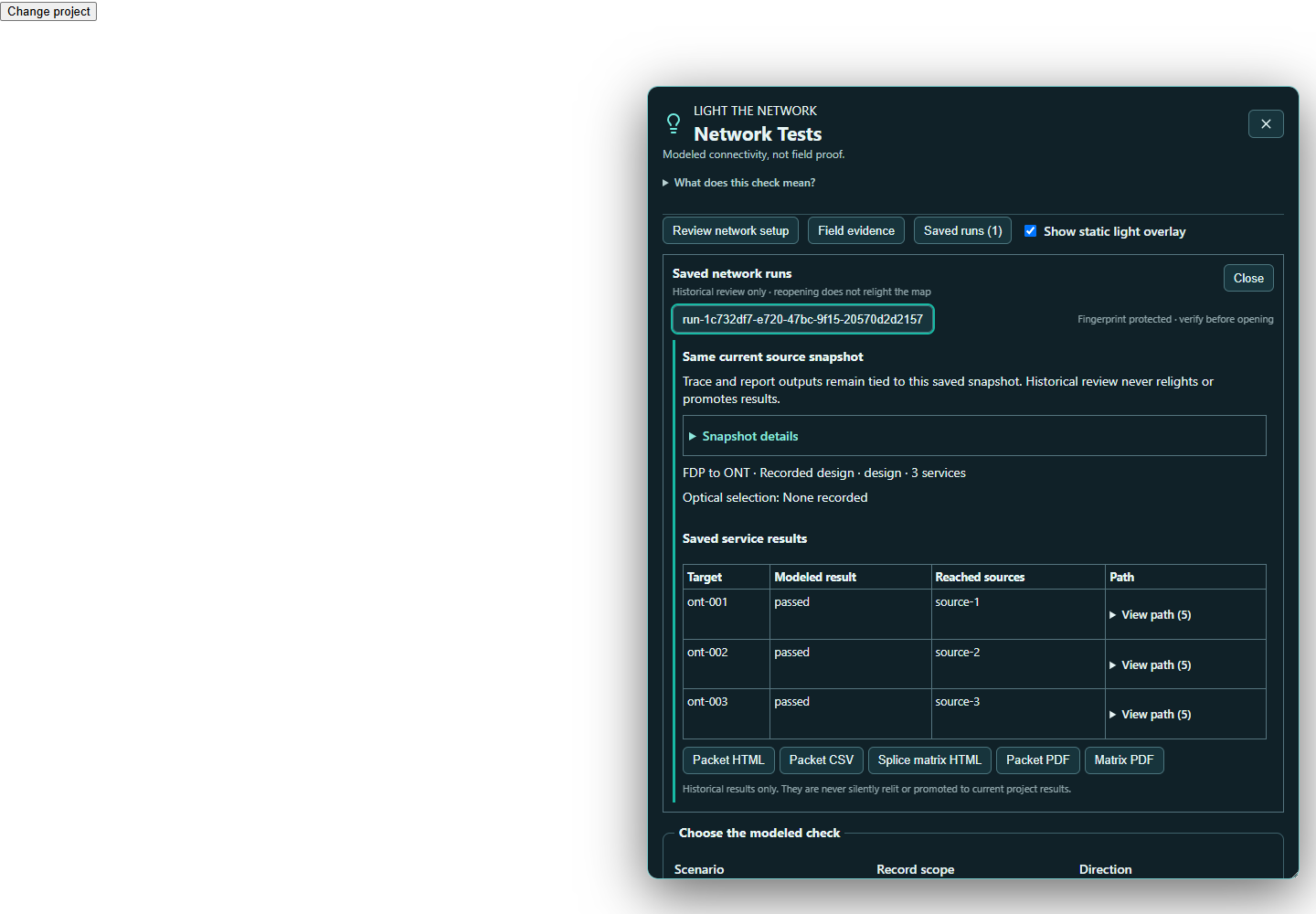
A saved run captures the source and result used for a completed check. Reviewing it later must not rewrite history to match today's project.
- Complete the intended Network Test, including any explicit optical profile and packet context.
- Choose Save test run. Cancelled or limited runs cannot be saved, and read-only projects cannot record a new run.
- Save the project. Save test run is a project edit, not a replacement for the normal Save command.
- Open Saved runs and select a run. FiberAtlas checks its stored source and result identities before showing details.
- Read Same current source snapshot or Historical / stale snapshot. Even a matching source is still a historical result.
- Expand Snapshot details for scope, source and target IDs, time, application/build identity, and report information.
- Export the historical packet or matrix from that run when needed. Check the historical label and scope before sharing.
History does not relight the map
Opening a saved run clears the active highlight and does not relight the current project. Original path references do not bind themselves to similarly named objects after the project changes. Adding another saved run or changing an ordinary save timestamp does not alone make the underlying source stale.
Capacity and portability
History is bounded to 100 runs, 16 MiB per encoded run, and 64 MiB aggregate encoded run payload. Captured attachments are repeated in each relevant run. If a limit is reached, the new run is refused; existing history is not silently removed. Native projects carry history; ordinary GIS/CSV and scoped copies are not full history backups.
↑ ContentsCHAPTER 17
Record measurements and field observations
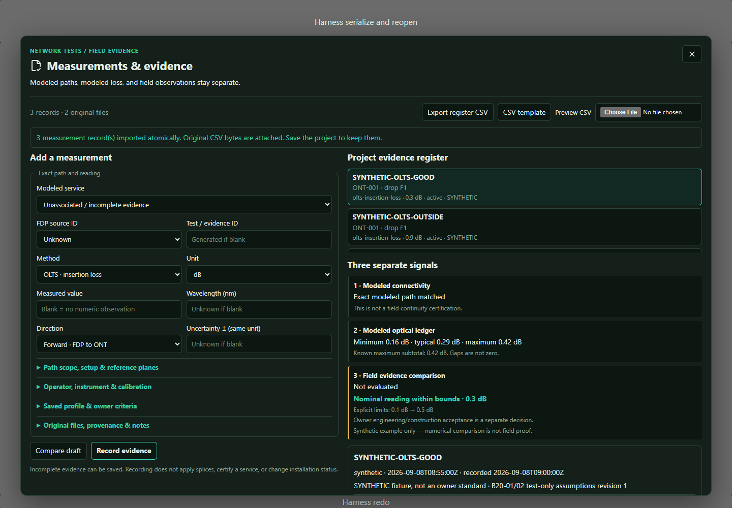
Field evidence preserves what someone entered or imported. A modeled path, a modeled optical ledger, and a measured observation remain three separate signals.
- Open Network Tests, choose the intended source/service scope, and select Field evidence.
- Choose the modeled service if known, or retain an unassociated/incomplete record for later review.
- Select the measurement method and compatible unit. Enter the value, wavelength, direction, and observation time only when known.
- Review Path scope, setup & reference planes. Keep source and target boundaries, reference planes, setup identity, and reference method exact.
- Add operator, instrument model and serial number, calibration reference and due date, and uncertainty when supported by the evidence.
- Choose a saved profile and explicit owner criterion with its source and revision if a comparison is intended.
- Review original attachments, provenance, and notes. Compare the draft if useful, then choose Record evidence and save the project.
Storage versus comparison
Incomplete evidence can be stored. A complete comparison needs compatible scope, method, wavelength, direction, unit, criterion, timezone-bearing time, instrument/calibration information, uncertainty, and verified attachment references. Missing conditions remain unevaluated.
Method matters
OLTS insertion loss compares in dB and OPM power in dBm. OTDR files, splice-machine estimates, continuity checks, inspection, and manual notes are not interchangeable with those comparisons. Negative apparent insertion-loss readings are retained for review rather than silently discarded or accepted. Synthetic evidence remains labeled synthetic.
↑ ContentsCHAPTER 18
Import field evidence and retain originals
Use the app's current CSV template. Evidence import is preview-first and must preserve incomplete states and original source information.
- In Field evidence, choose CSV template. Use the exact current headers rather than rebuilding the schema from memory.
- Where possible, record and export one example first to obtain valid scope IDs. Do not guess fingerprints or match a path by a display name.
- Prepare UTF-8 comma-separated data using period decimal separators and properly escaped quoted cells. Keep stable IDs and JSON snapshot cells intact.
- Use an explicit Z or numeric offset for observation timestamps. If the timezone is unknown, retain the original local text in the supported local-time field and mark its timezone unknown.
- Choose the CSV and review the preview, samples, and issue list. Fix every blocking issue, including those beyond the displayed detail limit.
- Cancel without changing the project, or commit the validated batch as one history transaction. Save the project to retain the records and embedded original CSV.
- Use Export register CSV for record data and snapshots. Use the native project when original attachment bytes must travel with the evidence.
Import limits
CSV limits are 5 MiB, 10,000 data rows, 64 columns, 10,000 characters per cell, and 1,000 retained issue details. The screen shows the first 100 row/detail entries and discloses truncation. Duplicate or existing IDs, invalid records, unsafe quoting, and formula-like cells can block commit.
Attachment limits
Supported originals include PDF, CSV, TXT, SOR, JSON, PNG, JPG/JPEG, and WEBP. Limits are 8 MiB per file, 32 MiB raw bytes in total, and 256 files. Files are retained with byte length, type, SHA-256, time, and provenance. Their contents are not automatically interpreted as a measurement or approval.
↑ ContentsCHAPTER 19
Correct, archive, and share evidence
Preserve the history of a field record. A correction should show what changed without erasing the observation it supersedes.
- Select the evidence record and inspect its current scope, source, status, and original attachments.
- Use the correction workflow to create a new record that supersedes the earlier one. Do not import another row with the same ID to overwrite it.
- Review both the earlier observation and the correction. Keep the original time, source, and provenance understandable.
- Archive a record when it should no longer be treated as active. Review archive and supersession state in the register.
- After changing the network or criterion, inspect stale-scope information. A previously matching observation must not silently become current for a different path.
- Use Save original copy to export a hash-verified original as opaque data. Inspect the intended filename and destination.
- Save the native project. Before sharing it, review its embedded originals and saved-run history as well as its current map.
Integrity is separate from interpretation
A verified hash means the stored bytes match the retained original. It does not validate an instrument's reading or interpret a SOR file. Missing, tampered, or unverified originals block a complete evidence evaluation rather than being replaced by a similarly named file.
Choose the right handoff
The evidence-register CSV includes record data and snapshots but not original attachment bytes. Ordinary asset, route, quantity, equipment, service, KML/KMZ, GeoJSON, and shapefile exports are not complete evidence exports. A scoped copy may disclose omissions; retain a complete native archive for controlled review.
↑ ContentsCHAPTER 20
Compose map sheets in Print Workspace
Print Workspace prepares presentation and report output from a defined source. Review the source and page scope before refining appearance.
- Open Print from the intended project, folder, Area, or Phase. Check the source, visible geometry, and any organizational boundary.
- Choose the required paper size, orientation, and layout. Use fit/reset controls to frame the intended content.
- Use the sheet controls to include, exclude, reorder, duplicate, or remove pages. Review any index, grid, or corridor output in sequence.
- Position map and information panels deliberately. Use layout Undo/Redo for presentation changes.
- Open or save a print layout only for the intended purpose. A layout file is not a native project backup.
- Review preflight messages and selected report sections before generating a PDF.
- Open the generated PDF and inspect every page for expected scope, labels, legend entries, units, clipping, overlap, and blank or repeated pages.
Legend and paper limits
Long conduit descriptions can exceed a detailed legend panel. The application can disclose omitted entries; enlarge or reposition the panel or use the full Route Footage inventory. A compact category/count legend is not a complete specification schedule.
Output verification
RC1 PDF output has been exercised, but physical printers and their drivers are not yet verified. Check a physical proof on your own printer before relying on its scaling. Raw provider basemap tiles are not included in exported project packages; review the output's reference and geometry disclosures.
↑ ContentsCHAPTER 21
Print splice matrices and technical packets
Choose the report that answers the reader's question. A case matrix, a project-wide matrix, and a scoped network packet can cover different records.
- For a splice matrix, select the exact case or the intended folder/project scope and use its Print Splice Matrix action.
- Review case IDs, cable ends, logical trays, recorded mappings, exclusions, and conflict disclosures. Keep suggested drafts out of recorded instructions.
- Use booklet output where offered and inspect its page sequence and scope. Do not assume a booklet implies a particular physical binding or imposition.
- For a current Network Test, select the report context and choose Packet HTML, CSV, or PDF.
- For a saved run, export from Saved runs so the packet uses the captured source and remains labeled historical.
- Open the output and compare a few exact path IDs and matrix references with the source. Review every PDF page before handing it off.
Historical matrix scope
A saved run's matrix output covers the whole captured project's recorded matrix. It is not necessarily limited to the service or folder scope used for the trace. The packet's matrix references identify the cases and trays used by its paths.
Paper and machine-readable detail
The packet CSV carries route detail even when a paper-saving route appendix is off. Repeated PDF creation can change container metadata; use report/source fingerprints rather than assuming byte-identical PDFs. A changed checksum or unsupported historical report version blocks export instead of guessing a repair.
↑ ContentsCHAPTER 22
Import and export GIS and project data
Choose an exchange format for its intended content. Native project data, GIS geometry, inventory CSV, evidence CSV, and printed reports are not interchangeable.
- Preserve the original incoming file. Open Import and choose a supported format, such as KML or KMZ, through the actual menu offered.
- Review import messages, invalid records, scope, and any loss or compatibility disclosure before committing the result.
- Inspect names, types, coordinates, folders, style references, and counts in the imported project. Do not assume similar names represent the same stable object.
- Save a native working copy under a new name after review.
- Open Export and choose the appropriate output: KML/KMZ, GeoJSON, Shapefile ZIP, supported CSV, or scoped native/project output.
- Choose Basic Sharing or Full Record detail and Entire Project or Visible Map Content where offered. Review any excluded content.
- Export to a new filename. Open it in the intended recipient's viewer and compare geometry, names, counts, and expected attributes.
Format boundaries
GeoJSON uses WGS84 geometry. Shapefile output is a ZIP with the required sidecars and manifest; keep the package together. A Full Record GIS export is still not the complete native graph, saved-run history, or embedded evidence archive.
Round-trip expectations
A successful export does not promise perfect round-tripping through every viewer. Confirm compatibility with the actual receiving software. The earlier KML/KMZ defect was repaired before RC1; retained native verification covered a specific Full Record / Entire Project case, while other permutations have source-level tests.
↑ ContentsCHAPTER 23
Understand Shared Workspace and read-only files
Shared Workspace organizes separate Work Files and aggregate views. RC1's verified support remains local storage; real shared-drive and multi-workstation use still needs testing.
- Preserve your local project before opening or creating a Shared Workspace.
- Inspect the listed Local Projects and Work Files. Distinguish the active writable file from a viewed or read-only file.
- Refresh status before opening a file for work. Respect a lock or ownership message that identifies another active writer.
- Use one writer per Work File. Other files can be reviewed read-only without becoming editable copies of the same source.
- Check which source files are available and included before relying on aggregate quantities or printing.
- Save the active Work File successfully before switching. If switching stops because saving failed, resolve that save instead of assuming the new file is active.
Locks are not a merge system
Do not delete another session's lock or force a foreign-owned file into writable mode. A stale-lock or takeover workflow needs deliberate review and preservation of the prior file. The presence of shared-work controls is not evidence that simultaneous edits merge safely.
Recommended evaluation practice
Use local disposable copies for practice and keep independent backups. A synchronized folder, shared drive, or network outage can behave differently from local storage. Report the exact environment when helping test this boundary; do not treat the current software tests as multi-user acceptance.
↑ ContentsCHAPTER 24
A structured practice session
Use the application's built-in fictional samples to explore without customer information. You are testing software behavior, not validating a construction design.
- Save and close your current work. Open Help and choose Open Beta 1.7 network trace sample for a synthetic 100-home exercise.
- Select a source, inspect exact source positions, and run the recorded-design Network Test. Read assignment details rather than only the total count.
- Use Quick Light Trace from a service endpoint. Check that clearing the highlight leaves the project unchanged.
- Open the Splice Lab and review a known mapping. On a saved practice copy, create a draft, inspect it, cancel it, and confirm recorded mappings are unchanged.
- Use Help's Open Beta 1.8 optical sample for a fictional 32-branch PON. Review the branch, wavelength, profile, and known or missing inputs.
- Save a completed run, save the project, close normally, reopen that exact copy, and inspect Saved runs.
- Change one documented input on a further copy and compare its history label. Export a historical packet and confirm it still identifies the original source.
- Write down one confusing step, missing explanation, or useful result and share it through https://fiberatlas.app/feedback.
Sample labels identify their origin
The Help actions retain their Beta 1.7 and Beta 1.8 names in RC1. Their data is fictional. Optical values are test-only assumptions, not manufacturer specifications or owner criteria.
Useful feedback
Include the exact sample, app/build identity, operation, expected outcome, actual result, and whether the result repeats. If you intentionally introduce a cut or wrong assignment, clearly label that alteration.
↑ ContentsCHAPTER 25
Troubleshooting by symptom
Preserve the current file and the smallest reproducible example before changing the environment. A failed operation must not be silently counted as completed.
No Trial email
Check the submitted address and spam/junk folder. Wait for the current request before requesting again; requests are rate-limited. Use the newest confirmation message. If it still fails, email support with the time and address used; do not publish confirmation links.
Download link expired or installer mismatch
Request a fresh confirmation email for expired website access. Compare the actual package hash with the current download page. Do not run a mismatched package. Another download does not restart the app Trial.
Basemap is blank, but my records remain
Check internet access, selected provider, and any provider error. Online reference service availability is separate from the local project. Do not move geometry just to make it align with a failing background map.
The wrong tool keeps placing points
Choose the Select arrow. Escape cancels a current draft, while selecting the arrow leaves persistent placement mode.
An edit, Apply, import, or save is disabled
Check read-only state, Trial status, required fields, occupied positions, and the displayed review errors. Do not remove locks or falsify required values to bypass a block.
Green path, but incomplete or failed service
Inspect the intended source, reached source, exact strand/port mapping, and scenario/lifecycle. Reachability, correct assignment, optical evaluation, and measured evidence are different results.
History is stale or export is blocked
Review the saved run's source identity and report version. A changed project can make history stale. A failed integrity check requires preserving the original for investigation, not editing its checksum.
Output is clipped or a legend omits entries
Review paper, orientation, scope, panel dimensions, and omission notices. Use complete inventories where needed and inspect the new PDF. Physical printer behavior must be checked separately.
↑ ContentsCHAPTER 26
Keyboard and command reference
These are application-shell shortcuts in RC1. Text fields, open dialogs, the Splice Lab, and Print Workspace can consume keys in their own context.
Files
Ctrl+N: New project. Ctrl+O: Open. Ctrl+S: Save. Ctrl+Shift+S: Save As. File operations can still require a filename, confirmation, or valid writable state.
History
Ctrl+Z: Undo. Ctrl+Y or Ctrl+Shift+Z: Redo. These operate in the active supported editing context; they do not retroactively change an already-shared output file.
Workspace
Ctrl+K: Focus project-tree search. Ctrl+Shift+M: Toggle Map Focus. Use the same Map Focus command to return the tree and properties panels.
Drawing
Enter: Finish an active route or measurement after at least two points, or a boundary after at least three vertices. Escape: Cancel the active draft or supported move. Delete: Delete the selected feature after confirmation when writable and outside a typing field.
Context actions
Right-click opens supported context actions. Context Menu or Shift+F10 exposes supported splice-matrix actions on focusable project/container entries. Not every control has the same context menu.
Finding help
Open Help and search by the task, such as autosave, quantities, associations, or privacy. Open About FiberAtlas to copy the precise app and build identity. Use Report a problem - local file to prepare a reviewed support note.
When a shortcut seems inactive
Finish or cancel the active dialog, check keyboard focus, and use the visible command to confirm availability. A disabled action can reflect read-only or Trial protection rather than a broken key binding.
↑ ContentsCHAPTER 27
Terms, file types, and capacity limits
Use the label attached to the result. A number or color without its source and scope is easy to misread.
Native project
.fiberatlas is the working record, including supported graph relationships, evidence originals, and saved history. A print layout, GIS export, or CSV is a separate artifact with narrower content.
Recorded, draft, and installed
Recorded is a user-authored project relationship. Draft is a proposed or simulated change. Installed describes a separately documented lifecycle state. Apply Splices records mappings; it does not create field-completion proof.
Unknown, incomplete, stale, and historical
Unknown means no value or relationship is established. Incomplete means required information is missing. Stale means the source or scope has changed. Historical means the result belongs to an earlier captured source even if that source still matches.
Connectivity, optical ledger, and measured evidence
Connectivity follows explicit modeled relationships. The optical ledger calculates from selected documented inputs. Measured evidence stores an observation and its provenance. None automatically supplies engineering or owner acceptance.
Saved-run bounds
Maximum 100 runs; 16 MiB per encoded run; 64 MiB aggregate encoded run payload. Repeated captured attachments increase storage. The complete project can be larger because of its ordinary records and encoding overhead.
Field-original bounds
Maximum 256 files, 8 MiB per file, and 32 MiB total raw original bytes. Supported extensions: PDF, CSV, TXT, SOR, JSON, PNG, JPG/JPEG, WEBP. An original's presence does not interpret its contents.
Evidence CSV bounds
5 MiB input, 10,000 data rows, 64 columns, 10,000 characters per cell, 1,000 retained issue details, and 100 displayed preview/detail entries. A truncated display does not waive errors in later rows.
↑ ContentsCHAPTER 28
Get help and give useful feedback
Your practical experience helps decide what to improve. Public Trial users can email feedback without an invitation code.
- Open https://fiberatlas.app/feedback. Choose a bug, an improvement, or what worked well. The link opens a draft in your email app; you review and send it yourself.
- If an email app does not open, use your usual email service and address the message to fiberatlasapp@gmail.com.
- For a reproducible issue, include Help > About version/build, Windows version, display scaling, the task, shortest repeatable steps, expected result, and actual result.
- Optionally use Help > Report a problem - local file. Choose a type, enter the report, select Review report, then Save local report.
- Read the local note before attaching it to your message. Add a screenshot only when it is useful and you have reviewed what it reveals.
- If you are an invited tester, you can also use your existing Beta Hub sign-in for tracked reports and missions.
What is sent
The local problem-report command saves a file; nothing is automatically sent. Its automatic context is limited to the displayed allowlisted build/runtime fields. Your typed text is included, so remove private names, addresses, geometry, project paths, credentials, or unrelated records before sharing.
Privacy in ordinary use
Project files are local. Basemaps, address search, accepted location use, and links you open can contact online services. Native project copies and reports can contain sensitive content; review the actual artifact and its historical attachments before sharing.
↑ ContentsCHAPTER 29
RC1 scope and documentation record
This manual is the task-first reference for the public FiberAtlas Beta 2.0 RC1 Trial. It is based on the matching release source and retained verification records, with application images labeled by their origin.
Current release
Public version 0.1.0-beta.20-rc1; embedded app version 0.1.0-beta.20-dev.1; source commit 6fe9a30d58b174a575badf062f689f99f58e4f1c. The source checks on September 11, 2026 passed 2,029 tests, with zero failures or skips. Setup and Portable have exact published hashes and valid timestamped signatures.
What RC1 adds to the older manual
Equipment and port connections, the expanded Splicing Laboratory, Quick Light Trace and Network Tests, optical review, saved-run history, field measurements and original attachments, report workflows, conduit descriptions, and clearer workspace controls.
Evidence boundaries
The RC1 Sandbox checks cover installation, associated project-file launch, current-user uninstall, and preservation of an existing project file. Prior-candidate checks remain dated evidence for their own scope. The manual's procedures are source-grounded; not every procedure was repeated as a fresh RC1 native walkthrough.
Known limits
Verified RC1 support is bounded to Windows 11, local storage, and PDF output. Broader display scaling, upgrade combinations, shared drives, multi-workstation locking, physical printers, and long practitioner workflows need more testing. Optical catalogs and criteria require reviewed source data.
Separate products
FiberAtlas Build, Records, Field, and PoleLab are separate development or planned work. They are not included as released functionality in this public Trial manual.
Document revision
Revision 1, prepared September 14, 2026 (UTC). It supersedes the older Alpha 14.5a and Beta 1 v2 manuals as the RC1 reference. Historical PDFs remain available separately. Current corrections, evidence, and support are linked from https://fiberatlas.app/manual and https://fiberatlas.app/testing.
↑ Contents